This was actually a really fun project that Jon and I did for our Interfacing Digital Electronics course. The objective was to use an Optek OPB745 reflective object sensor and a Freescale HCS12 microcontroller to read Morse code from printed paper. The project was very open-ended, and it was up to each team to decide how to generate the printed Morse code, decode it on the microcontroller, and present the output to the user.
PC Software
Although the majority of the project was the design and development of the actual Morse code reader device, we were also responsible for devising a way to generate the actual printed Morse code messages that our device would be capable of scanning. I believe that some of the teams simply used Morse code fonts or online generators for this purpose. Our team developed a GUI PC application to quickly and easily generate highly customizable Morse code messages for us.
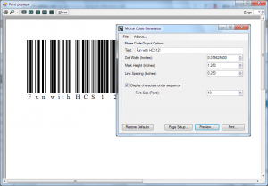
I wrote the Morse code generator application in C#/.NET using the Windows Forms framework, having recently picked up on the technology from my previous co-op experience. The software allows you to enter a string that it will then draw the Morse code for. The sizing of the fundamental unit (equivalent to a dot’s mark length or an inter-character space’s length) is selectable in real world units (i.e., inches), as is the height of the marks. The lengths of dashes, spaces between words, and spaces between characters are keyed appropriately from the fundamental unit size (i.e., ratios of 3:1, 3:1, and 7:1, respectively). The software also provides the option to augment the Morse code with the corresponding English characters. Words wrap appropriately to multiple lines, and lines can continue onto multiple pages, if necessary. Finally, the application offers page setup and print preview windows to make sure that the Morse code sequence is printed exactly as intended.
In our project, we opted to use very elongated Morse code marks in order to make it very easy for the user to keep the scanner device on track while swiping the code. This scheme looks very similar to bar codes, and in fact it would be only a minor decoding change in the firmware to enable the device to read bar codes.
Hardware
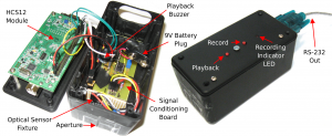
The hardware aspect of this project is actually very simple. The analog frontend consists of nothing other than the OPB745, a low pass filter, and a comparator. The output from the comparator is connected to one of the input capture pins on the Freescale HCS12 microcontroller development module. In addition, there are two buttons and an LED for basic user interaction with the device. One of the buttons starts or stops a scan sequence (with the LED indicating that the device is “recording”), while the other button allows the user to play back the Morse code audio of the scanned, normalized sequence through a small piezo beeper. The development board also contains a DB9 connector attached to an RS-232 level converter connected to one of the microcontroller’s UART pins. This peripheral allows us to provide a textual user interface to the device from a PC (or serial serminal) that actually displays the decoded output of the scan, as well as some additional functions. All of this is powered via a 9V battery and LDO voltage regulator.
The project housing seeks to provide appropriate lighting conditions for the OPB745 to read the bar code. This means that the sensor should be isolated from ambient light. Furthermore, it should have an aperture that is small enough such that a single mark from the Morse code printout will fill the entire field of view of the sensor. This will ensure that the sensor will always reach the maximum full-black or full-white reflective state as it scans over the Morse code.
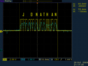
The following scope capture shows the comparator output from the analog section as the sensor swipes over a Morse code segment containing the name “Jonathan”. Notice how the pulse width differences between dots and dashes are clearly distinguishable.
Firmware
The firmware on the microcontroller is responsible for decoding and processing all of the information received from the light sensor. With the analog frontend already discretizing the information from the sensor into digital pulses, the primary job of the firmware is simply to accurately measure the pulse widths, distinguish between the different types of marks and spaces, and decode the Morse code scheme.
Measuring the pulse widths, in our case, is trivial. We used the timer input capture peripheral to automatically measure the time between edges in hardware and trigger an interrupt.
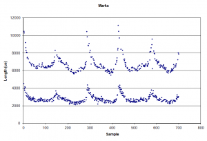
The real challenge, then, is determining how these pulse widths correspond to the different types of marks (dots and dashes) and spaces (intra-character, inter-character, and between words). The plots below demonstrate some timing results that were captured from scanning five lines of Morse coded text. Clearly, the human aspect of performing a swipe yields very high variance in speed, and hence pulse width, both within a swipe and between swipes. It is therefore insufficient to set fixed thresholds for differentiating between the different types. Actually, these captures happen show relatively good data, and a quick glance shows us that, for this particular swipe, appropriate threshold values could indeed be selected. Nonetheless, we sought a more robust solution that would accurately decode a wide range of swipe speeds and deviations.
Our solution ended up using a decaying average to adapt to the speed of each swipe:

Fortunately, this type of average has a very efficient implementation in code, as the halving is simply a right shift. Furthermore, this accumulate/shift operation can be performed ongoing as each new reading comes in. For example, consider the following code snippet:
|
1 2 3 4 5 6 |
int average = firstReading; void updateAverage(int newReading) { average = (average + newReading) >> 1; } |
Our algorithm always scales any new pulse width reading into the fundamental unit length before accumulating so that we ensure that we are averaging the same type of value. The algorithm begins in the initial state by assuming that the first pulse is the fundamental unit length. If a pulse is encountered that is significantly shorter, then we recognize that we must have encountered only dashes previously, and that the new reading is actually a dot. The accumulated average is re-scaled accordingly to reflect the new information. At the end of each swipe (detected by a timeout in edge detections), the collected data is decoded and the decaying average is reset.
Once we have this adaptive reference for our fundamental unit length, we can begin to distinguish the different types of marks and spaces by using thresholds based upon this moving reference. For example, because we know that a dash should be three times longer than a dot, we could set a threshold at two times the dot length. Any mark under this threshold will be considered a dot, and any mark above the threshold will be considered a dash. Similarly, for spaces, a 2X fundamental length threshold is used to distinguish between inter-character spaces and intra-character spaces, and a 6X fundamental length threshold is used to distinguish between intra-character spaces and spaces between words.


